Table of Contents
- Overview
- How does laser cutting work?
- How does CNC punching work?
- What are the key differences?
- Laser vs punching: comparison table
- Cost and volume: where the crossover sits
- Tolerance, edge quality and thickness limits
- Combining both processes
- Two real parts, costed both ways
- Lead time and tooling
- When should you choose laser cutting?
- When should you choose CNC punching?
- FAQ
Overview
Laser cutting and CNC turret punching are the two workhorse processes in flat sheet-metal fabrication. Both create internal and external profiles by removing material, yet they differ fundamentally in mechanism, cost structure, and ideal application range. Selecting the wrong process can double per-part cost or add weeks to lead time — making this one of the earliest and most consequential decisions in any sheet-metal project.
Quick answer: Fiber laser cutting handles complex contours, tight radii and design changes with no tooling cost, so it suits prototyping and low volumes. CNC turret punching is faster per part on high-volume, simple profiles and can form, tap or emboss in the same cycle — the crossover usually lands at 2,000–5,000 pieces.
How does laser cutting work?
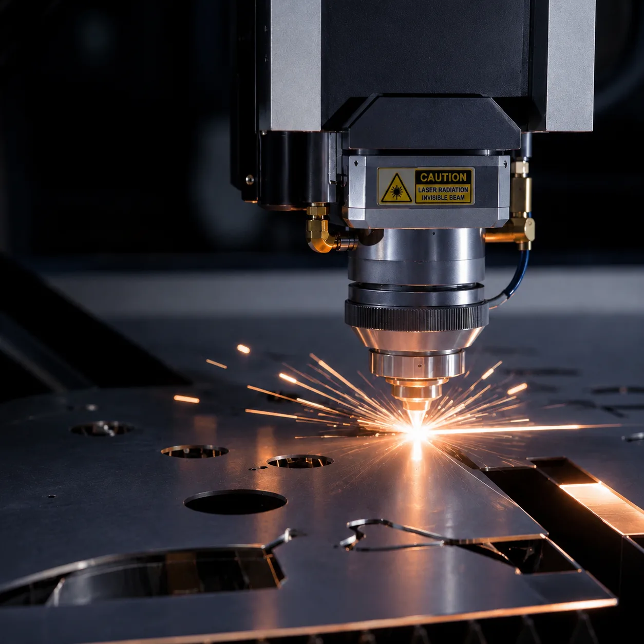
A focused fiber or CO₂ laser beam melts and vaporizes material along a programmed path. A coaxial assist gas (nitrogen, oxygen, or air) ejects the molten kerf. Because no physical tool contacts the workpiece, laser cutting excels at intricate contours, tight radii, and fine details that would be impossible with mechanical methods.
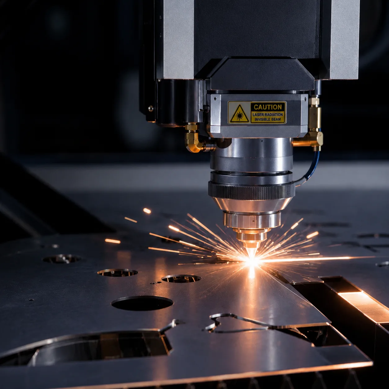
- No tooling cost — programs are generated directly from DXF/DWG files
- Kerf width: 0.1–0.3 mm, enabling very tight tolerances (±0.05 mm achievable)
- Material thickness range: 0.3–5.0 mm (typical for production fiber lasers up to 6 kW); industry range extends to 25 mm+ with higher-power sources
- Cuts virtually any 2D profile without geometric constraints
How does CNC punching work?
A CNC turret punch press strikes the sheet with hardened tooling mounted on a rotating turret. Each punch creates a specific shape — round holes, louvers, embossments, countersinks — by shearing or forming the metal. For larger contours, the machine nibbles along the profile with a punch-and-die pair, stepping small increments per stroke. Because the turret already holds two dozen or more tools, a panel with many different hole sizes can run without a single tool change.
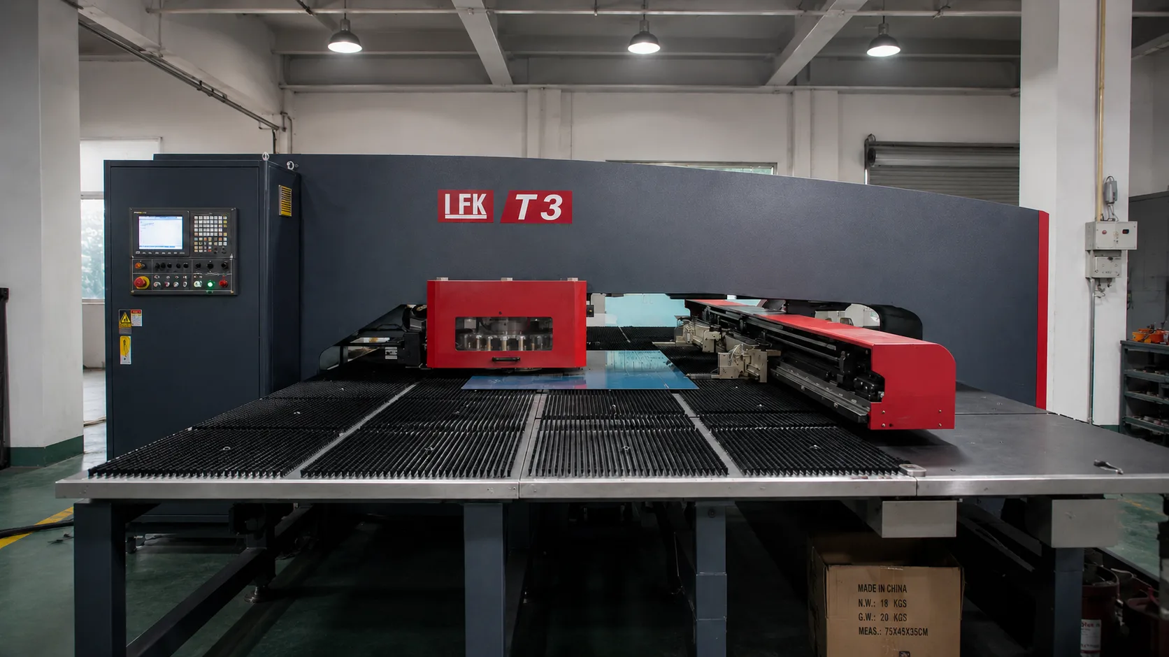
- Tooling cost per shape: $200–$10,000, amortized over high volumes
- Cycle time for simple hole patterns: 10× faster than laser on thin-gauge material
- Can form features: louvers, countersinks, embossments, extruded holes, 3D forms
- Best suited for 0.5 mm to 3.2 mm mild steel, aluminium, and stainless
What are the key differences?
The choice between laser and punching comes down to geometry complexity, production volume, material thickness, and required features. Below is a side-by-side comparison.
Both processes run in the same building at WERIX, so the choice is made on part economics rather than on what a supplier happens to own.
Laser vs punching: comparison table
| Parameter | Laser Cutting | CNC Punching |
|---|---|---|
| Tooling cost | None (program only) | $200–$10,000 per tool |
| Minimum feature size | 0.1 mm kerf width | 1.0× material thickness (typical round hole) |
| Thickness range | 0.3–5.0 mm (typical 6 kW); up to 25 mm+ with higher-power sources | 0.5–3.2 mm (optimal); practical ceiling ≈6.35 mm (1/4 in) |
| Forming capabilities | None — flat cut only | Louvers, emboss, countersinks, extruded holes, tapping |
| Best volume | 1–2,000 parts | 2,000–50,000+ parts (crossover ≈2,000–5,000) |
| Geometric complexity | Unlimited contours | Limited to tool shapes + nibbling |
| Typical tolerance | ±0.05–0.13 mm (ISO 9013 governs the cut quality class) | ±0.05–0.10 mm on pierced holes |
| Edge quality | Smooth, minimal burr; oxide edge on mild steel if cut with oxygen | Clean shear with a rollover–burnish–fracture–burr section; may need deburring |
| Material utilisation | 75–85% typical (no tool-clearance constraints) | 65–80% typical (tool clearance and slug clearance reduce nesting) |
| Nesting flexibility | High — parts can share edges freely | Lower — clearance required between hits and around slugs |
| Setup time | ~5 min (load DXF) | 15–30 min (tool change + program); 1–2 weeks if new tooling must be made |
| Typical cost per part | Lower at low volume, flat as volume rises | Higher on first parts, falls steeply once tooling is amortised |
Combining both processes
On many production parts the cheapest route is not one process but both. A turret punch can pierce every standard hole and form the louvers, embosses or extruded features in a single fast pass, and a laser then cuts the outer profile and any complex internal cutouts. The punch does the high-volume repetitive work where it is fastest; the laser does the contours where tooling would be expensive or impossible.
This hybrid approach is common on enclosure panels, server racks and control cabinets — parts with hundreds of identical holes plus an irregular outline. It lets a shop avoid a large custom contour tool while still getting punching throughput on the repetitive features. The trade-off is a second setup and a second machine queue, so it pays only when the contour tooling saving outweighs the extra handling.
- Below ~500 parts: laser is almost always cheaper — no tooling, no setup, instant design changes
- 500–2,000 parts: the gap narrows; complex or hole-dense parts still favour laser, simple high-hole-count parts start to favour punching
- 2,000–5,000 parts: the crossover zone — quote both, because part geometry decides the exact point
- Above 5,000 parts: punching is normally the lower cost per part; progressive die stamping becomes worth evaluating past roughly 20,000–50,000 parts
Two real parts, costed both ways
The economics are easiest to see on real numbers. Both examples below are representative production parts, costed as laser-cut versus punch-cut, with the tooling amortised into the unit price.
Case 1 — perforated vent panel. 1.5 mm cold-rolled mild steel, 400 × 300 mm, 240 round holes of 4 mm, no formed features, tolerance ±0.2 mm, annual volume 12,000 pieces. The hole count is what decides it: a turret punch indexes one 4 mm tool and hits the pattern at roughly 200–380 holes per minute, so the whole panel is done in a couple of strokes per hole with no contour tool needed — the standard round tool is a stock item. Laser would have to pierce all 240 holes individually and would spend far longer on the machine. Punching wins clearly here, despite the tooling, because the pattern is repetitive and the tolerance is loose.
Case 2 — prototype enclosure bracket. 2.0 mm 5052 aluminium, 180 × 120 mm, six 5 mm holes, one complex internal cutout with a 3 mm internal radius, tolerance ±0.1 mm, quantity 150 pieces for a first build. The complex cutout with a tight internal radius is what decides it: a punch tool for that contour would be custom, take 1–2 weeks to make and cost four figures, and would only ever run 150 times. Laser cuts every profile from the DXF with no tooling, holds the ±0.1 mm, and the 150-piece run finishes in a single sheet-setup day. Laser wins here, and the design can still change without scrapping a tool.
Lead time and tooling
Lead time follows the tooling decision. Laser cutting has no tooling step, so a first article is typically ready in 1–3 days from a released drawing, and design changes cost nothing but a new program.
CNC punching absorbs two extra steps on a first run: programming and, if a custom tool is needed, tool manufacture — typically 1–2 weeks for a new shape. That puts first parts for punching at roughly 3–5 days when stock tooling is used, or longer when a custom tool is ordered. The gap closes completely once tooling exists: on a repeat order the punch runs faster per part and, at volume, ends up delivering sooner than laser because the cycle time dominates.
When should you choose laser cutting?
Laser cutting is the clear winner when your design features intricate geometry, tight tolerances, or very thin or thick material that falls outside the turret punch range.
- Complex outlines with small internal radii (< 1 mm)
- Prototype or low-volume runs (1–500 parts, and usually up to ~2,000)
- Material thickness above 3.2 mm or below 0.5 mm
- Parts requiring no formed features — purely flat profiles
- Quick-turnaround projects where setup time matters
When should you choose CNC punching?
CNC punching dominates when the part includes formed features, high hole density, or production volumes that justify tooling investment.
- Parts requiring louvers, extruded holes, or embossments
- High hole-density panels (hundreds of perforations)
- Production runs exceeding ~2,000 identical parts (crossover commonly 2,000–5,000)
- Thin-gauge material (0.5–3.2 mm) with simple profiles
- Applications where cost per unit is the primary driver
Send us the drawing and the annual volume and we will tell you which process is cheaper — including the crossover point between them. Upload your CAD for a quote and a process recommendation within 24 hours.
Standards referenced: folded into our process selection are ISO 2768-1 general tolerances, which govern the general tolerances we hold when a drawing does not call out individual limits, and ISO 9013, which classifies the dimensional and edge quality of thermal cuts.
Cost and volume: where the crossover sits
Cost is the decision driver on most projects, and it splits into two parts that behave in opposite directions. Laser cutting has almost no setup cost and a relatively high cost per metre of cut. Punching has a large one-off tooling cost and a very low cost per hit. Plot the two against volume and they cross once — that intersection is the break-even point.
In practice the crossover for a simple bracket or panel with standard holes lands between 2,000 and 5,000 pieces. Below it, laser wins because there is no tool to amortise. Above it, punching wins because the tooling is spread across enough parts to disappear into the unit price, while the faster cycle keeps machine time down.
- Below ~500 parts: laser is almost always cheaper — no tooling, no setup, instant design changes.
- 500–2,000 parts: the gap narrows. Complex or hole-dense parts still favour laser; simple, high-hole-count parts start to favour punching.
- 2,000–5,000 parts: the crossover zone — quote both, because part geometry decides the exact point.
- Above 5,000 parts: punching is normally the lower cost per part, and progressive die stamping becomes worth evaluating past roughly 20,000–50,000 parts.
Three cost items are easy to miss when comparing quotes. First, deburring: a nibbled punch contour leaves tool marks and a slight bow that often needs a secondary operation, while a laser edge usually does not. Second, utilisation: laser nests at 75–85% and punching at 65–80%, so the same part consumes more material on the punch — see nesting for why. Third, programming and tooling lead time: a new custom punch tool takes 1–2 weeks to arrive, which is a schedule cost as much as a money cost.
Tolerance, edge quality and thickness limits
The two processes are close on tolerance but differ on where that tolerance is easy to hold and what the edge looks like.
Tolerance. Laser cutting holds roughly ±0.05–0.13 mm (typically ±0.10 mm on thin sheet) and the achievable figure is standardised by the cut-quality class in ISO 9013, which classifies thermal-cut edges by perpendicularity and mean roughness. Punching holds ±0.05–0.10 mm on pierced holes, but the accuracy depends on the die clearance — a worn or loose tool drifts, so tolerance holds best on a fresh tool in a well-maintained turret.
Edge quality. A laser edge is smooth with minimal burr; on mild steel cut with oxygen it carries a slight oxide layer that must be removed before painting or welding. A punched edge is a clean shear, but microscopically it has four zones — rollover, burnish, fracture and burr — and the burr on the exit side usually needs a deburring pass. On a visible edge, deburring is a real line-item.
Thickness. This is the clearest split. Punching is optimal between 0.5 mm and 3.2 mm and practical up to about 6.35 mm (1/4 in); thicker material requires disproportionate force and tooling. Laser covers 0.3–5.0 mm on a typical 6 kW production machine and extends to 25 mm+ on higher-power sources — so anything above ~6 mm is laser territory by default.
- Parts requiring louvers, extruded holes, or embossments
- High hole-density panels (hundreds of perforations)
- Production runs exceeding ~2,000 identical parts (crossover commonly 2,000–5,000)
- Thin-gauge material (0.5–3.2 mm) with simple profiles
- Applications where cost per unit is the primary driver
FAQ
Co-authored by

Senior Process Engineer
Tom has spent more than a decade on the shop floor turning drawings into parts that run right the first time. He leads DFM reviews at WERIX Metal, sets the bending and tooling strategy for every new project, and writes the guides engineers actually reach for when they are sizing a part late at night.
View profile
Industrial & Product Design Engineer
Julia takes a product from the first sketch to a sheet metal design that can actually be made. She sits between the customer’s concept and our press brakes — modelling enclosures and brackets in CAD, running early DFM passes, and choosing the material and finish that will still look right two years down the line.
View profile
Mechanical Engineer
Jack takes the drawings that arrive in the morning and works out how they will actually run on our machines by the afternoon. He owns the mechanical side of a project at WERIX Metal — checking bend sequences against real tooling, sizing hardware and fasteners, and making sure a bracket that looks simple on screen still assembles cleanly on the bench.
View profileParts we make for this topic
Ready to Start Your Project?
Get DFM feedback and a quote within 24 hours. No minimum order quantity.