Table of Contents
Where Your Money Goes in Sheet Metal Fabrication
A typical sheet-metal part's cost breaks down into five buckets: raw material (30–45%), cutting (10–20%), bending (10–15%), finishing (10–20%), and setup/handling (5–15%). Most cost-reduction efforts focus on material, but the biggest savings often come from design decisions that reduce setup time, eliminate unnecessary operations, and consolidate multiple parts into one. This guide covers the eight most impactful strategies, ranked by typical savings.
Quick answer: Sheet metal cost splits roughly into material (30–45%), cutting (10–20%), bending (10–15%), finishing (10–20%) and setup and handling (5–15%). The largest savings rarely come from chasing cheaper material: relaxing non-critical tolerances, standardising holes and fasteners, reducing bend count and consolidating assemblies cut cost without affecting quality.
1. Right-Size Your Material and Gauge
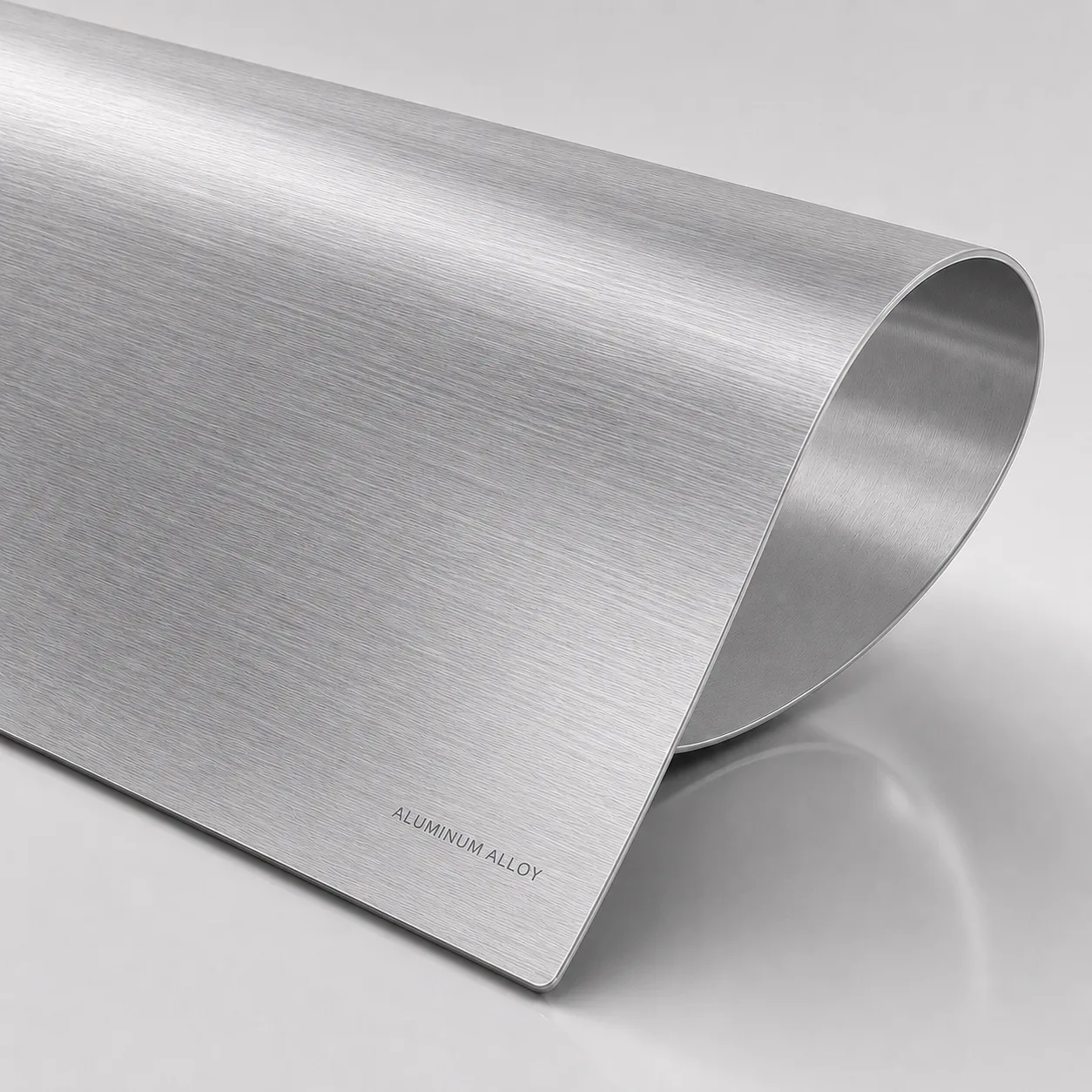
Raw material accounts for 30–45% of part cost. Specifying a thicker gauge than structurally necessary, or using a premium alloy where a standard one works, directly inflates your BOM. Common over-specifications include using 316 stainless when 304 suffices (20–30% cost penalty), or specifying 2.0 mm when 1.5 mm meets structural requirements (15–20% material savings plus faster cutting and bending).
- Run a basic FEA or hand-calculation to confirm minimum required thickness before specifying gauge
- Use standard stock sizes (0.8, 1.0, 1.2, 1.5, 2.0, 2.5, 3.0 mm) — non-standard gauges carry mill surcharges
- Consider CR steel over stainless for non-corrosive indoor applications — 60–70% cheaper
- Optimize nesting layout: ask your fabricator for a nesting analysis — tightly nested parts can save 5–15% on material utilization
2. Relax Non-Critical Tolerances
Over-tolerancing is the single most expensive design mistake in sheet metal. Specifying ±0.05 mm on every dimension when ±0.2 mm is functionally adequate forces the fabricator into slower processes, tighter inspection, and higher scrap rates. The rule: only tolerance critical functional dimensions — mating interfaces, alignment features, and seal grooves. Use general tolerance blocks for everything else.
| Operation | Standard Tolerance | Precision Tolerance | Cost Premium for Precision |
|---|---|---|---|
| Laser cutting (position) | +-0.15 mm | +-0.05 mm | +15-25% |
| Bending (dimension) | +-0.3 mm | +-0.15 mm | +15-25% |
| Bending (angle) | +-0.5 deg | +-0.25 deg | +10-20% |
| Hole diameter (punched) | +-0.10 mm | +-0.05 mm | +20-30% |
| Overall length | +-0.2 mm | +-0.1 mm | +20-30% |
In our experience, 80% of a typical sheet-metal part's dimensions can safely use standard tolerances. Only 20% — the functional interfaces — need precision. As an illustrative example: on a 20-dimension part, this distinction could mean the difference between a $4.50 part and a $6.00 part.
3. Design Bends Efficiently
Every bend adds setup time (die change, program adjustment) and cycle time. Parts with 8+ bends can cost 2–3× more than an equivalent design with 4 bends. Before adding a bend, ask whether the same function can be achieved with a simpler geometry.
- Reduce the number of bends: every bend beyond the first adds $0.10–$0.50 in setup and cycle time
- Standardize bend radii across the part — using the same radius for all bends allows a single die setup
- Maintain minimum flange length (4T + bend radius) to avoid requiring specialty tooling
- Avoid bends close to holes or edges — maintain a gap of 3T minimum to prevent distortion
- Use joggle bends or offsets sparingly — they require a second pass or specialty tooling
4. Standardize Holes, Fasteners, and Hardware
Every unique hole diameter, fastener type, or hardware insertion adds tooling and setup time. Standardizing on common sizes across your product family dramatically reduces NRE and setup costs.
- Use standard PEM hardware (S, CLS, SP series) rather than custom fasteners — they stock globally and insert without custom tooling
- Limit hole diameters to 3–4 standard sizes per part (e.g., M3, M4, M5, M6 clearance holes)
- Use self-clinching studs instead of welded studs where possible — faster insertion and no heat distortion
- Group similar operations: all holes of the same size should be punched in a single turret station pass
5. Choose the Right Cutting and Forming Process
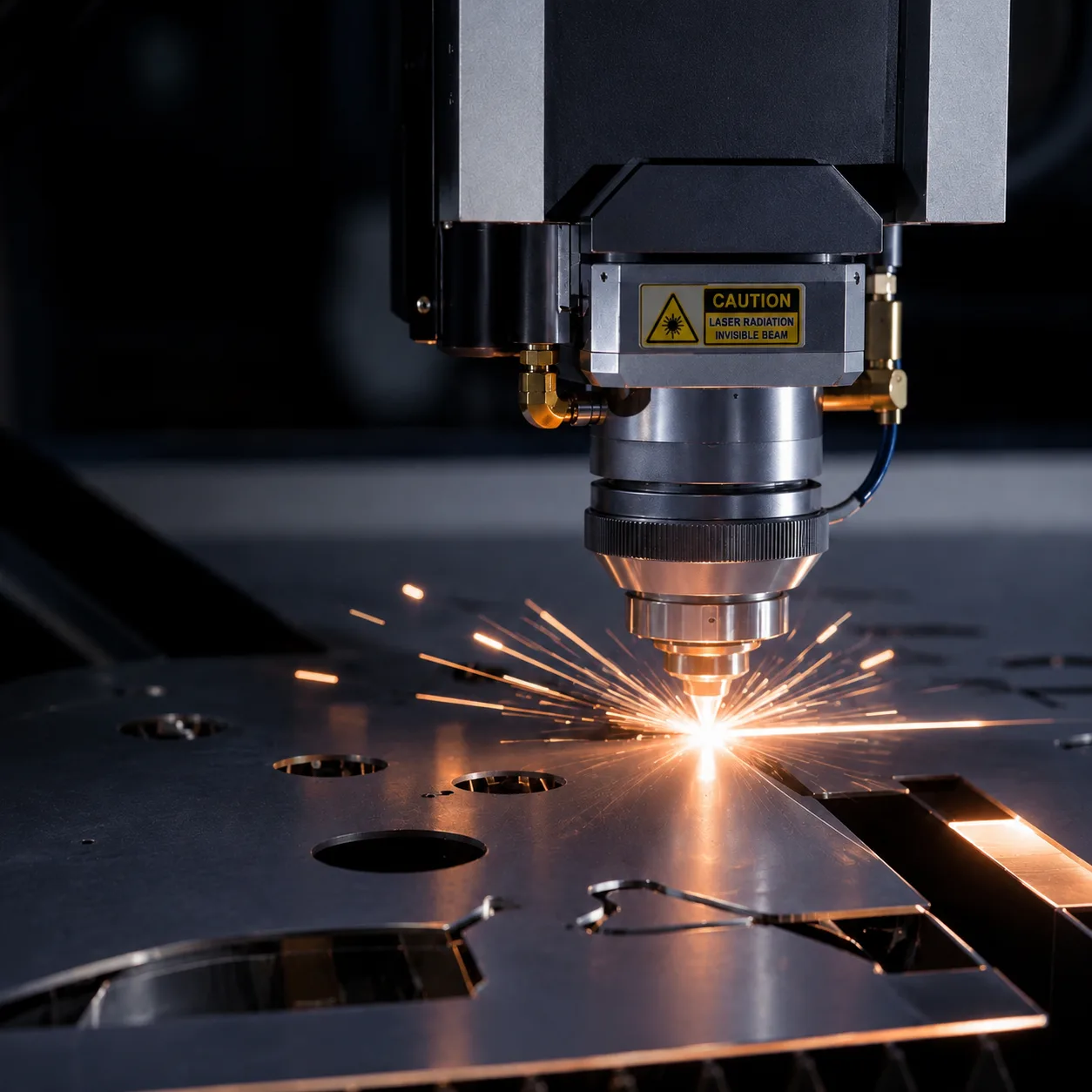
Process selection directly affects per-part cost at volume. Laser cutting dominates at 1–500 parts (no tooling), but turret punching becomes cheaper above 500 parts on thin-gauge material with simple profiles. For simple geometries, stamping becomes cost-competitive with laser-cut-and-bend once volume justifies die investment — the exact crossover depends on part complexity. Understanding these crossover points prevents overpaying at volume.
| Process | Best Volume Range | Setup Cost | Per-Part Cost Trend |
|---|---|---|---|
| Laser cutting + bending | 1–500 pcs | $0 (program only) | Flat — no volume discount |
| Turret punch + bending | 500–50,000 pcs | $200–$10,000 per tool | Decreases with volume |
| Progressive stamping | 5,000–1,000,000+ pcs | $2,000–$30,000 per die | Sharply decreases with volume |
| Transfer die stamping | 10,000–500,000+ pcs | $5,000–$30,000 | Lowest per-part at high volume |
6. Consolidate Multi-Part Assemblies
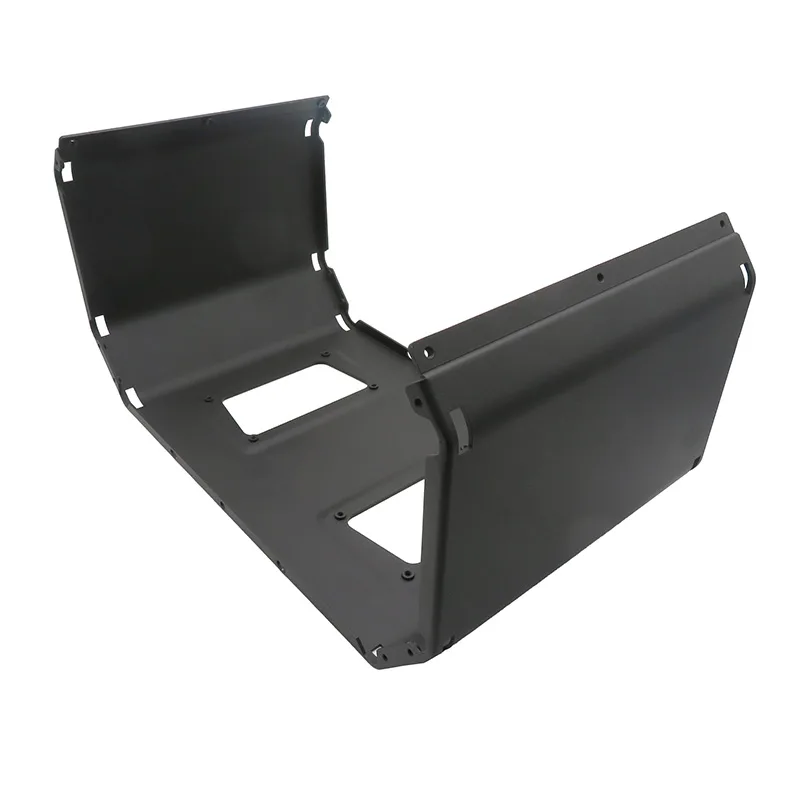
Each separate sheet-metal part in an assembly carries its own setup, cutting, bending, finishing, and handling costs — plus the assembly cost to join them. Often, two or three simple parts can be combined into a single more complex part that costs less than the sum of its components. Look for bracket-plus-panel combinations, folded enclosures that replace welded boxes, and tab-and-slot joints that eliminate fasteners.
- Replacing 3 separate brackets with 1 formed bracket saves 2× setup + 2× finishing + assembly labor
- Tab-and-slot joints eliminate spot welds and self-clinching hardware on non-structural connections
- Folded enclosures (single piece with 4+ bends) replace welded 5-piece boxes at 40–60% lower cost
- Ask your fabricator for a design-for-assembly (DFA) review — experienced engineers routinely find consolidation opportunities
Cost Savings Summary
The table below summarizes the eight strategies with typical savings ranges. Applying multiple strategies simultaneously yields compounding savings.
| Strategy | Typical Savings | Difficulty | When to Apply |
|---|---|---|---|
| Right-size material gauge | 15–25% | Easy | At design stage |
| Downgrade alloy where possible | 20–40% | Easy | At design stage |
| Relax non-critical tolerances | 15–30% | Easy | At drawing stage |
| Reduce number of bends | 10–30% | Moderate | At design stage |
| Standardize hole sizes & hardware | 5–15% | Easy | At design stage |
| Optimize nesting layout | 5–15% | Fabricator-side | At quoting stage |
| Choose correct process for volume | 20–50%+ | Moderate | At sourcing stage |
| Consolidate parts in assembly | 30–60% | Hard (redesign) | At architecture stage |
Tolerancing, gauge selection, and alloy choice require zero design changes — just a review of your current specifications. These three alone typically save 20–35% on part cost. Part consolidation requires redesign but delivers the largest absolute savings.
We will price your part as drawn and then flag the specific features that are driving cost. Upload your CAD for a costed quote with DFM savings notes in 24 hours.
Standards referenced: the tolerance advice in this guide follows ISO 2768-1 general tolerances; relaxing to its middle classes is one of the cheapest cost levers available.
FAQ
Co-authored by

Senior Process Engineer
Tom has spent more than a decade on the shop floor turning drawings into parts that run right the first time. He leads DFM reviews at WERIX Metal, sets the bending and tooling strategy for every new project, and writes the guides engineers actually reach for when they are sizing a part late at night.
View profile
Industrial & Product Design Engineer
Julia takes a product from the first sketch to a sheet metal design that can actually be made. She sits between the customer’s concept and our press brakes — modelling enclosures and brackets in CAD, running early DFM passes, and choosing the material and finish that will still look right two years down the line.
View profile
Mechanical Engineer
Jack takes the drawings that arrive in the morning and works out how they will actually run on our machines by the afternoon. He owns the mechanical side of a project at WERIX Metal — checking bend sequences against real tooling, sizing hardware and fasteners, and making sure a bracket that looks simple on screen still assembles cleanly on the bench.
View profileParts we make for this topic
Ready to Start Your Project?
Get DFM feedback and a quote within 24 hours. No minimum order quantity.