Table of Contents
Overview
Every custom metal part starts with the same question: which manufacturing process? For parts made from sheet or plate stock, the two dominant paths are sheet metal fabrication (laser cutting, punching, bending, welding) and CNC machining (milling, turning, and multi-axis subtractive manufacturing). They overlap on some geometries but diverge sharply on cost structure, material utilization, and design constraints. Choosing the wrong process can inflate per-part cost by 3–5× or add weeks to your timeline — especially when scaling from prototype to production.
Quick answer: Sheet metal fabrication is the faster, cheaper route for enclosures, brackets, panels and chassis — especially from one to a few thousand pieces, with no tooling cost and low material waste. CNC machining wins where you need tight three-dimensional tolerances, thick sections, threads or complex solid geometry. Many assemblies need both.
How does each process work?
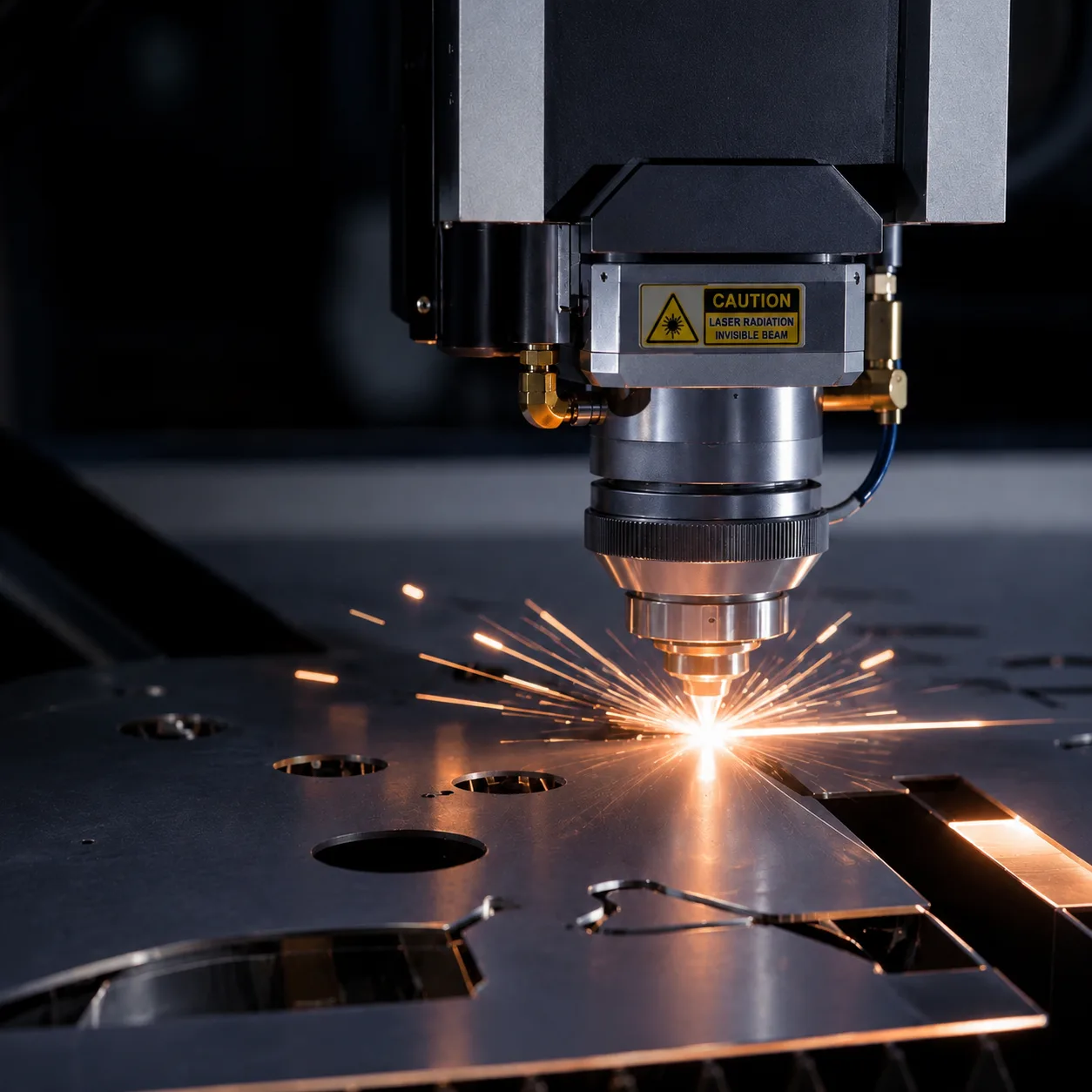
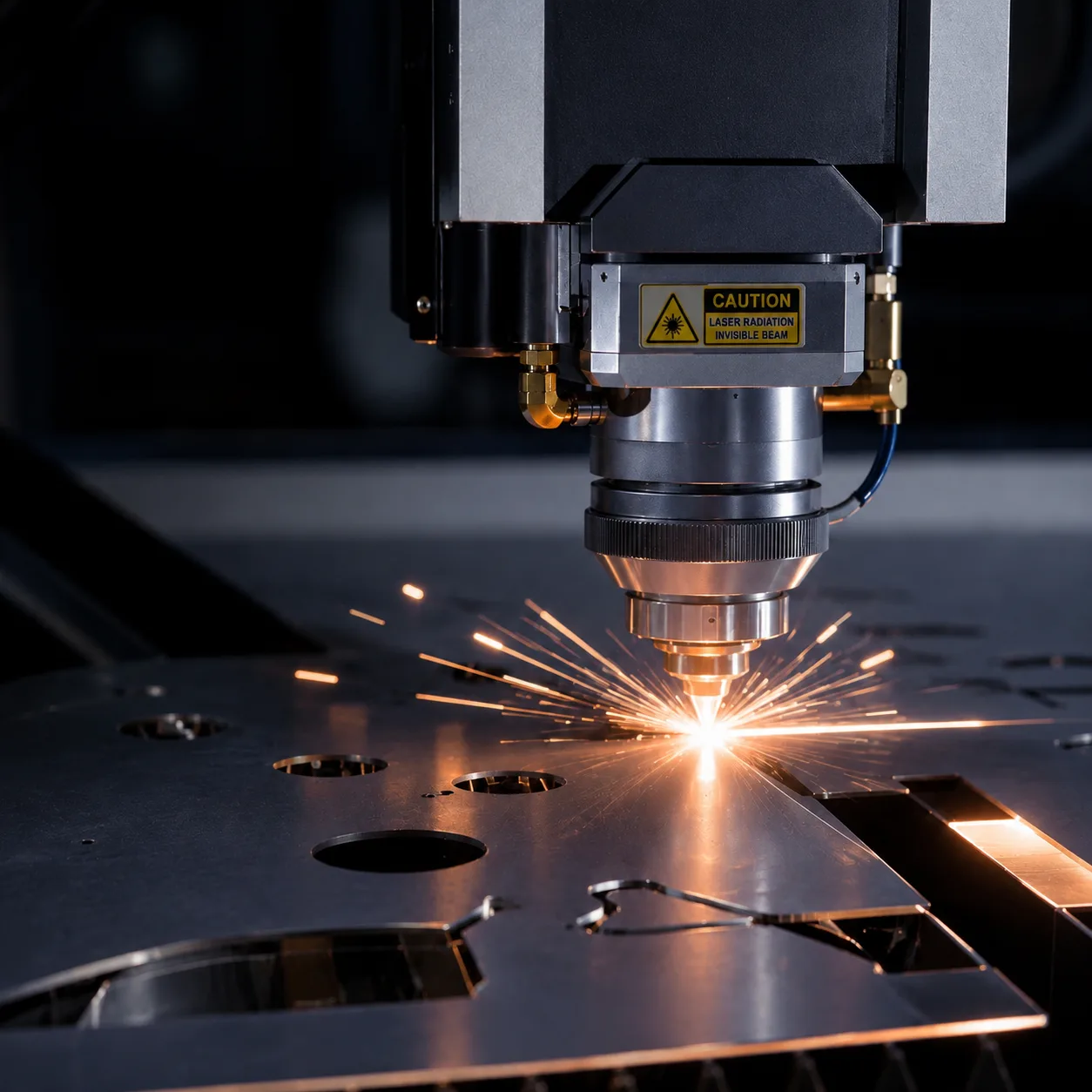
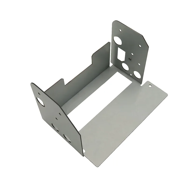
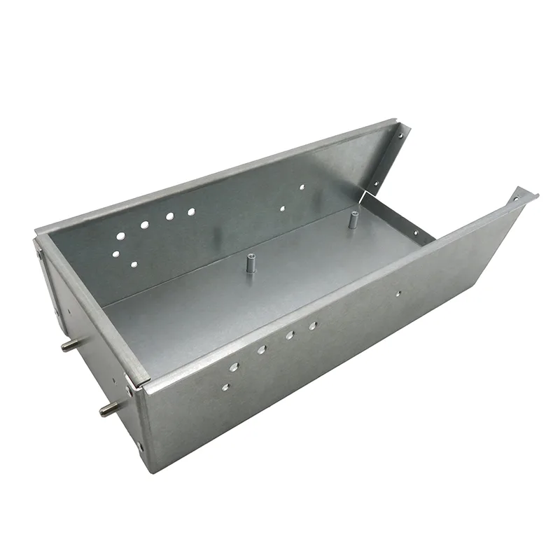
Sheet metal fabrication starts with flat stock (sheet or plate) and transforms it into 3D parts through a sequence of 2D cutting, forming, and joining operations. A fiber laser or turret punch cuts the flat profile from a nested sheet, a press brake bends the flat pattern into 3D geometry, and welding or fastening closes the final assembly. The key characteristic: material utilization is high (typically 70–85% with optimized nesting), and the process is inherently suited to hollow, lightweight structures — enclosures, brackets, panels, and chassis.
CNC machining starts with solid stock (bar, billet, or block) and removes material through rotary cutting tools to create the final geometry. A 3-axis mill handles prismatic parts; a lathe handles cylindrical parts; 5-axis machines handle complex organic shapes. Material utilization is often 10–40% for complex parts — the rest becomes chips. Machining excels at tight tolerances, complex 3D surfaces, and parts that need features impossible to form from sheet stock (deep pockets, undercuts, internal threads).
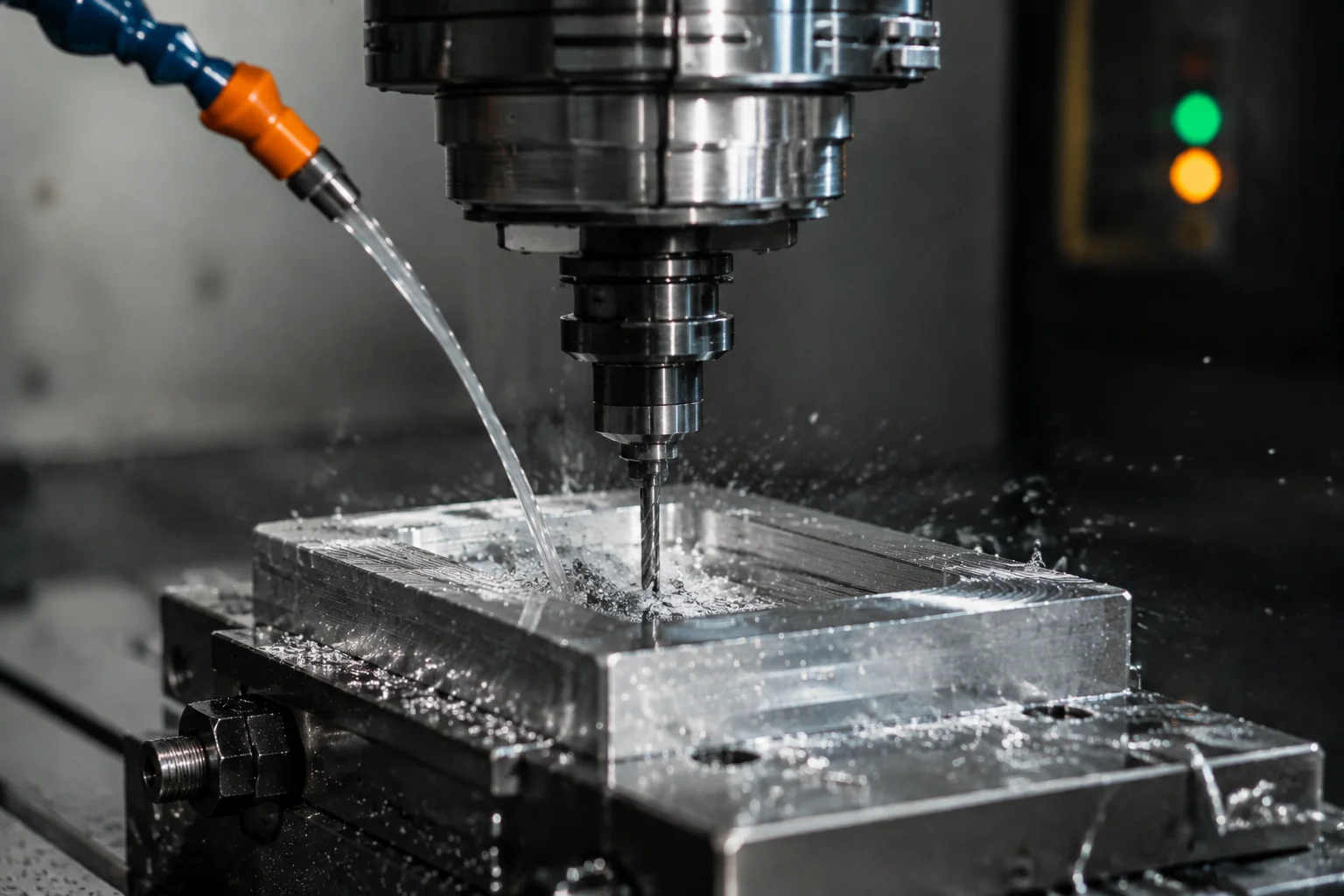
CNC machining starts with solid stock (bar, billet, or block) and removes material through rotary cutting tools to create the final geometry. A 3-axis mill handles prismatic parts; a lathe handles cylindrical parts; 5-axis machines handle complex organic shapes. Material utilization is often 10–40% for complex parts — the rest becomes chips. Machining excels at tight tolerances, complex 3D surfaces, and parts that need features impossible to form from sheet stock (deep pockets, undercuts, internal threads).
How do laser cutting and CNC machining compare on cost by volume?
The cost structures of these two processes diverge dramatically with volume. Sheet metal fabrication has low setup cost (no tooling for laser-cut parts, modest tooling for punches) but moderate per-part cost. CNC machining has zero tooling cost but high per-part cost due to machine time, tool wear, and material waste. The crossover point depends on part complexity — simple flat-and-bend parts favor sheet metal at almost any volume; complex prismatic parts may favor machining even at low volume.
| Quantity | Sheet Metal (typical bracket) | CNC Machining (typical bracket) | Notes |
|---|---|---|---|
| 1 piece | $30–$80 | $50–$150 | Sheet metal wins on simple geometries; machining competitive on complex parts |
| 100 pieces | $8–$20 each | $35–$80 each | Sheet metal 3–5× cheaper; no tooling amortization needed |
| 1,000 pieces | $4–$12 each | $25–$60 each | Sheet metal gap widens; consider punch tooling for further savings |
| 10,000 pieces | $2–$8 each | $20–$50 each | Sheet metal dominates; progressive die stamping can reduce cost further |
Cost Driver: Material Utilization
Sheet metal parts typically achieve 70–85% material utilization with optimized nesting. CNC machining often wastes 60–90% of the starting billet as chips. On a $5/kg aluminum part, this difference alone accounts for $2–$4 per part in raw material cost — before considering machine time.
Tolerance and Precision Comparison
CNC machining holds significantly tighter tolerances than any sheet metal process. A well-maintained CNC mill routinely holds ±0.025 mm on critical dimensions; sheet metal laser cutting achieves ±0.1 mm under standard conditions, and bending adds ±0.25–0.5 mm depending on material, thickness, and flange length. However, most sheet-metal applications — enclosures, brackets, panels — do not require machining-level tolerances.
| Parameter | Sheet Metal Fabrication | CNC Machining |
|---|---|---|
| Dimensional tolerance (cutting) | ±0.1 mm (laser), ±0.05 mm (precision) | ±0.025 mm (standard), ±0.01 mm (precision) |
| Bend angle accuracy | ±0.5° (standard), ±0.25° (precision) | N/A — no bending needed |
| Surface roughness (as-cut) | Ra 3.2–6.3 µm (laser edge) | Ra 0.8–1.6 µm (milled), Ra 0.4–0.8 µm (finished) |
| Positional accuracy | ±0.1 mm | ±0.025 mm |
| Flatness (per 300 mm) | ±0.2–0.5 mm | ±0.025–0.05 mm |
| Minimum feature size | 0.5 mm (laser kerf) | 0.3 mm (end mill diameter) |
Material Options Comparison
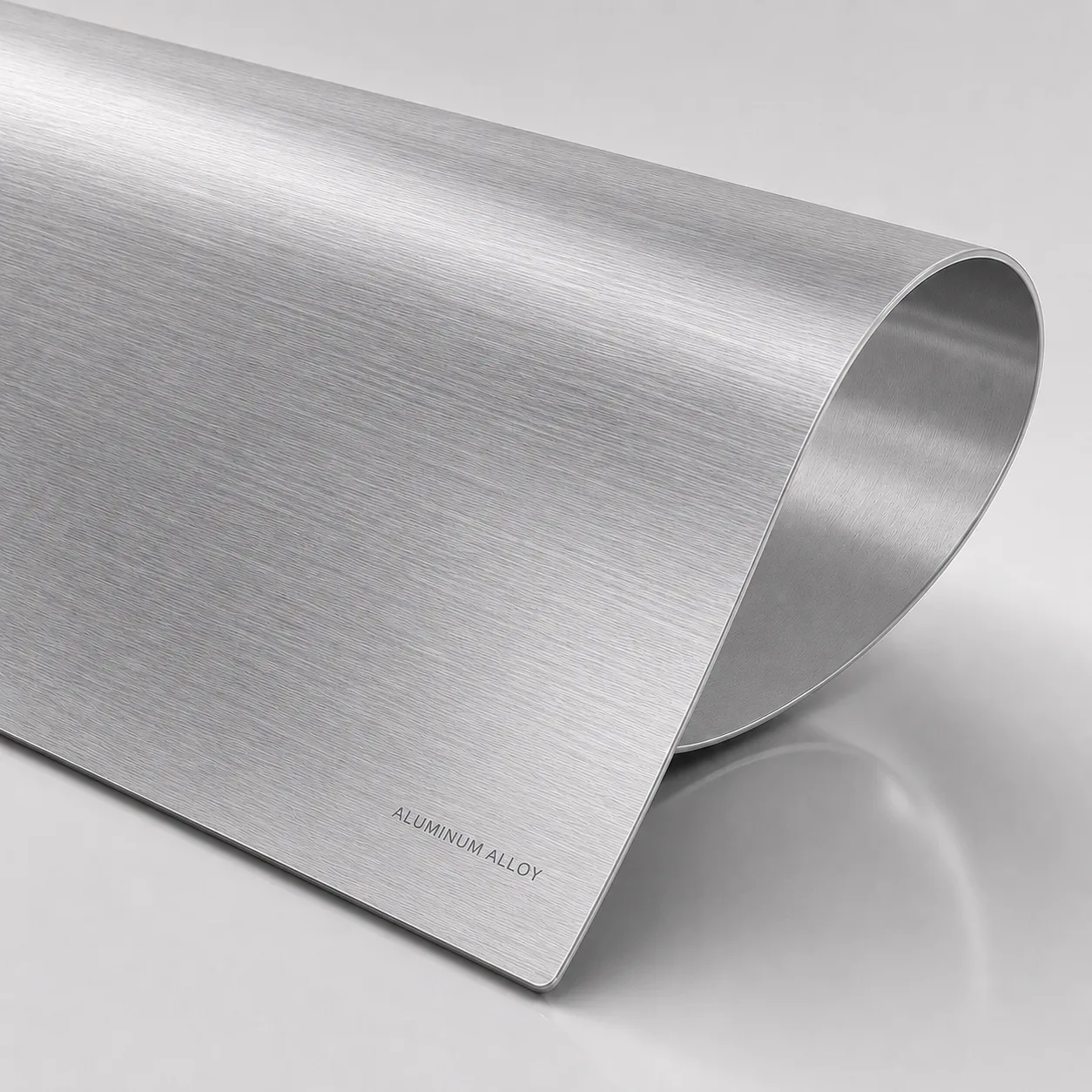
Both processes work with a wide range of metals, but each has material-related advantages and limitations. Sheet metal fabrication is constrained by available sheet/plate stock in standard gauges, while CNC machining can start from any solid stock geometry.
| Material | Sheet Metal Suitability | CNC Machining Suitability | Notes |
|---|---|---|---|
| CR Steel (SPCC, A36) | Excellent — low cost, highly formable | Excellent — easy to machine | Default for both processes |
| 304 Stainless Steel | Good — requires higher bend tonnage | Fair — work-hardens, requires rigid setup | Sheet metal preferred for enclosures |
| AL 5052-H32 | Excellent — highly formable | Excellent — easy to machine | Sheet metal preferred for lightweight enclosures |
| AL 6061-T6 | Fair — limited formability (2T–4T min radius) | Excellent — default machined aluminum | Machining preferred for structural parts |
| Copper C110 | Good — requires high-power laser (4+ kW) | Fair — gummy, requires sharp tooling | Sheet metal for bus bars |
| Titanium (Grade 2/5) | Poor — very high tonnage, springback | Fair — requires rigid setup, low SFM | Almost always machined |
Lead Time Comparison
Lead time depends heavily on complexity, volume, and whether tooling is involved. For prototypes (1–10 parts), sheet metal fabrication typically delivers faster because there is no tooling setup — a DXF file is loaded, the laser runs, the brake bends, and the part ships.
| Scenario | Sheet Metal Lead Time | CNC Machining Lead Time |
|---|---|---|
| Prototype (1–5 parts) | 3–7 business days | 5–10 business days |
| Small batch (10–100 parts) | 5–10 business days | 7–15 business days |
| Production (1,000+ parts) | 10–20 business days | 15–30 business days |
| With custom tooling (stamping) | 15–30 days (die fabrication) | N/A — no tooling needed |
Lead Time Advantage: No Tooling
For prototype and low-volume sheet metal parts, no tooling investment is needed — the laser program is generated directly from your CAD file. This eliminates the 2–6 week tooling lead time that can add weeks to stamped parts requiring die fabrication.
Design Complexity Limitations
Each process has inherent geometric constraints that engineers should understand during the design phase, not after quoting. Sheet metal parts must be developable — they start as flat stock and are bent into 3D shapes. CNC machining has virtually no geometric constraints — any shape that a cutting tool can reach is machinable.
- Sheet metal limitation: parts must unfold to a flat pattern — no undercuts, no closed channels (without welding)
- Sheet metal limitation: minimum bend radius is 0.5T–4T depending on material and grain direction
- Sheet metal limitation: holes near bends distort — maintain 3T gap from hole edge to bend line
- CNC machining limitation: deep pockets (depth > 4× diameter) require long, expensive tooling and slow feed rates
- CNC machining limitation: thin walls (< 0.8 mm in aluminum) vibrate and deflect during cutting
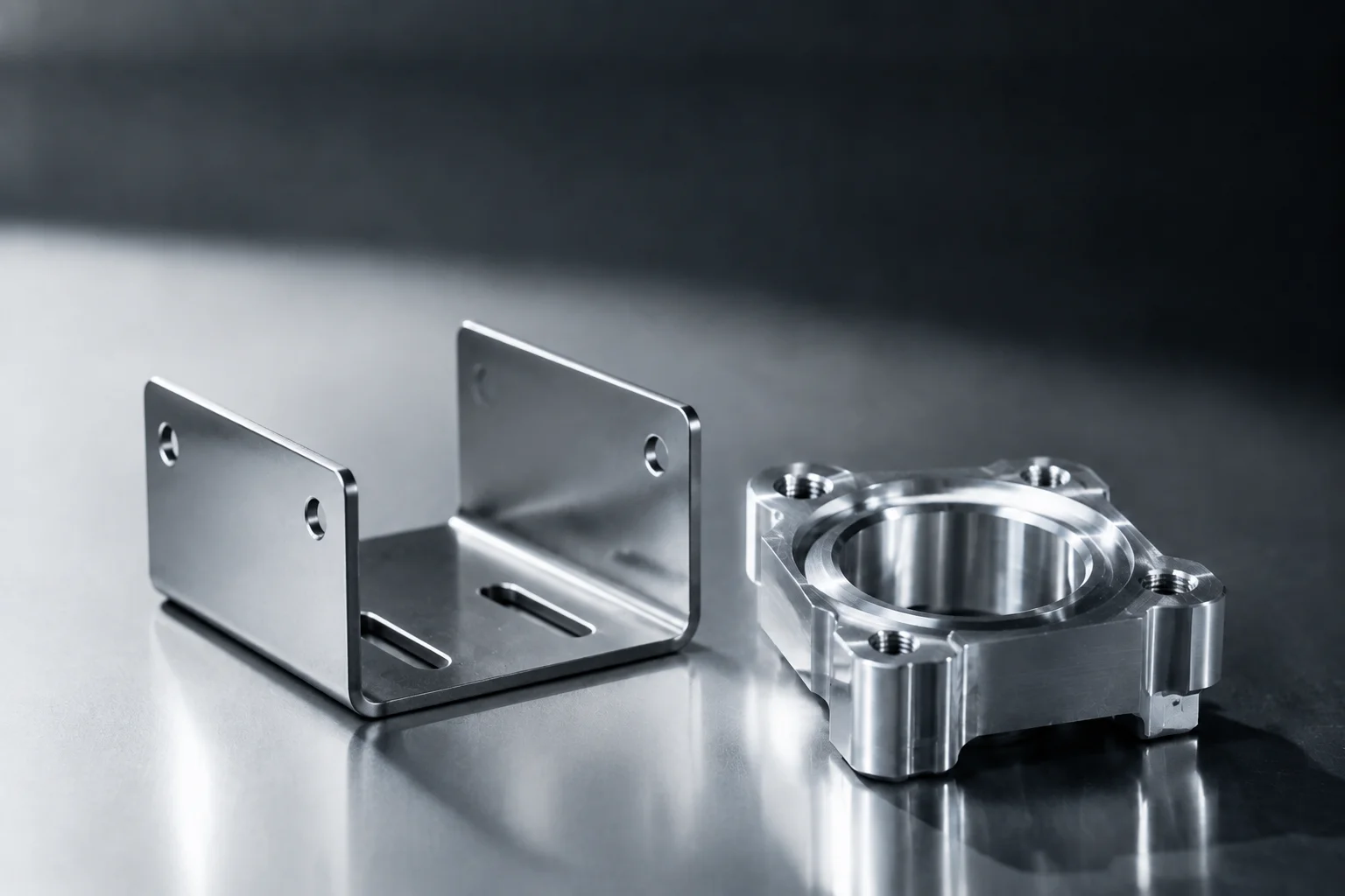
- Hybrid approach: many assemblies combine sheet metal enclosures with CNC-machined mounting plates
When should you choose which process?
The decision framework below distills our experience across thousands of projects into a practical guide. In many real-world assemblies, the optimal solution combines both processes — sheet metal for the enclosure or structural frame, CNC machining for precision interfaces or high-tolerance features.
| Decision Factor | Choose Sheet Metal | Choose CNC Machining |
|---|---|---|
| Part geometry | Hollow, thin-walled, flat-patternable | Solid, prismatic, complex 3D surfaces |
| Production volume | 10–100,000+ parts | 1–500 parts (cost-sensitive at volume) |
| Tolerance requirement | ±0.1 mm or looser | ±0.05 mm or tighter |
| Wall thickness | 0.5–6.0 mm | 1.0 mm+ (practical minimum) |
| Surface finish | As-cut + powder coat (Ra 6.3 µm) | Milled finish (Ra 0.8 µm) or better |
| Weight optimization | High — hollow structures | Moderate — solid stock with pockets |
| Cost priority | Per-part cost at volume | No tooling at low volume |
Hybrid Approach: Best of Both Worlds
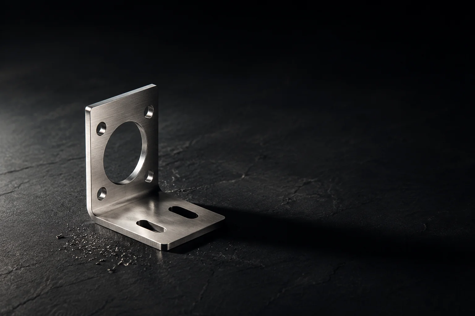
Many of our customers use sheet metal for the enclosure, brackets, and panels, then add CNC-machined inserts for precision mounting surfaces. The enclosure cost drops 60–70% versus a fully machined version, while the critical thermal interface maintains ±0.05 mm flatness.
Real-World Examples
Consider a rack-mount server chassis. Made entirely from CNC machining, a single unit would cost $300–$500 and require 8+ hours of machine time. The same chassis fabricated from sheet metal — laser-cut flat pattern, bent on a press brake, spot-welded at the seams — costs $25–$60 at volume and ships in 5–10 days.
Now consider a precision mounting bracket for a medical device that must hold ±0.025 mm on four dowel pin holes. Sheet metal cannot achieve this tolerance — the holes would need reaming after bending, adding cost and process steps. A CNC-machined aluminum bracket in 6061-T6 holds these tolerances routinely, and at a volume of 50–200 parts, the per-part cost ($15–$40) is justified by the functional requirement. The lesson: let the functional requirements — not habit — drive process selection.
Tell us the function and the volume and we will tell you which route costs less — and flag the parts that should be split between the two. Upload your CAD for a process recommendation and quote in 24 hours.
Standards referenced: where a drawing omits individual tolerances, we apply ISO 2768-1 general tolerances for linear and angular dimensions as specified for parts formed from sheet metal.
Now consider a precision mounting bracket for a medical device that must hold ±0.025 mm on four dowel pin holes. Sheet metal cannot achieve this tolerance — the holes would need reaming or jig boring after bending, adding cost and process steps. A CNC-machined aluminum bracket in 6061-T6 holds these tolerances routinely, and at a volume of 50–200 parts, the per-part cost ($15–$40) is justified by the functional requirement. The lesson: let the functional requirements — not habit — drive process selection.
FAQ
Co-authored by

Senior Process Engineer
Tom has spent more than a decade on the shop floor turning drawings into parts that run right the first time. He leads DFM reviews at WERIX Metal, sets the bending and tooling strategy for every new project, and writes the guides engineers actually reach for when they are sizing a part late at night.
View profile
Industrial & Product Design Engineer
Julia takes a product from the first sketch to a sheet metal design that can actually be made. She sits between the customer’s concept and our press brakes — modelling enclosures and brackets in CAD, running early DFM passes, and choosing the material and finish that will still look right two years down the line.
View profileParts we make for this topic
Ready to Start Your Project?
Get DFM feedback and a quote within 24 hours. No minimum order quantity.